Atomic Oxygen Simulation Systems
The ground-based radiation testing can be required in various space programs to identify the most stable spacecraft materials and coatings and to provide data that can be used to design spacecraft that can tolerate on-orbit material degradation. Simultek offers two types of Low Earth Orbit (LEO) environment simulators. Their difference is that only the source of atomic oxygen is installed in the first model (Compact). On the second model (Advanced), in addition to the source of atomic oxygen, at the request of the customer, UV sources are also installed, and a second source of atomic oxygen-microwave can be installed.
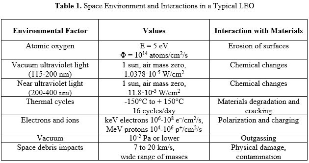
Atomic oxygen and atomic oxygen-induced processes are responsible for the most significant forms of polymer and other carbon-based materials deterioration and failure in LEO. While the exact details of the environment depend upon the specific orbit, distances, shape, and orientation, the LEO environment can be generally characterized by several major factors:
a) fast atomic oxygen with fluxes Φ ranging between (1-5)×1014 atoms/cm2/s at energies E of ~5eV
b) vacuum ultraviolet with its most intensive irradiation in the range 120-200 nm
c) the thermal cycling that all objects in LEO undergo and that can range between -1500C and + 1500C every 90 minutes
d) the hazards of the debris and micrometeoroids
e) irradiation by X-rays, electrons and proton particles, etc.
Among the above-mentioned factors, the AO factor plays the most important role in the erosion processes of organic materials. A variety of experimental techniques have been investigated as a means to study the interaction of materials with the LEO atomic oxygen environment. Exact simulation of the LEO environment is complicated by the fact that molecular oxygen must first be dissociated into atomic oxygen and then accelerated to the 5 eV energies associated with orbital impacts. Techniques for producing such a flux may utilize a high-energy laser to induce breakdown of molecular oxygen, followed by a rapid expansion of the resulting plasma, or grazing-incidence collisions between ion beams and metal surfaces, among other techniques.
 SimulTek has extensive experience in the successful design and manufacturing of space environment simulators, computer software and LEO environment simulation technologies. Four LEO Environment Simulator Systems for ground-based materials exposure to LEO factors (vacuum, AO beams, VUV/NUV and thermal cycling) have been designed, built and tested at SimulTek in the past ten years.
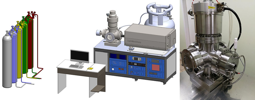
Simultek has designed, developed and manufactured several modifications of the simulator/test facility for accelerated laboratory testing of spacecraft materials and components in the conditions of the low Earth orbit (LEO) space environment. This simulator facility allows to simulate the synergistic effect of a number of LEO environmental factors, including: • ultra-high vacuum conditions (<10-7 Torr) • hyper-thermal Atomic Oxygen (AO) beams (5 eV) • Vacuum-Ultraviolet (VUV) radiation • Near-Ultraviolet (NUV) radiation (1-10 Suns) • thermal cycling between -1600C to +1600C. The AO simulator system uses the common principles of formation of continuous and pulsed Atomic Oxygen beams, VUV/NUV radiation, and thermal environment under high-vacuum conditions. The simulated LEO conditions can be controlled in-situ using an RGA mass-spectrometer, time-of-flight (ToF) technique, VUV detector/meter, and Quartz Crystal Microbalance (QCM) equipment. The AO simulator system can be used in many different applications, including ground-based accelerated testing and qualification of external spacecraft materials and coatings. The design of the AO system generally contains the following three major modules: • Vacuum chamber and vacuum pumping system • Pulsed CO2 IR laser with optical beam delivery and focusing system • Pulsed gas valve and synchronization system. This AO simulator has a 0.1 m3 vacuum chamber, an oil-free pumping system (two turbo pump FF-1200E and two scroll pump IDP-15). Vacuum chamber pressure is: • with the source “off” <10-7 Torr • with the source “on” 3×10⁻⁵ Torr. The samples mounted on the ~8” (~200 mm) Sample Holder Platform. Which is used is for heating, cooling, constant temperature maintenance, thermal cycling, and thermal shock testing of the samples. The effective temperature range that can be achieved using this system is from -160ºC to +160ºC. Temperature can be regulated and measured with 0.1ºC accuracy using the temperature controller. Each individual module of the AO environmental simulator systems is described below. AO Vacuum Chambers The vacuum chamber is manufactured from Stainless Steel 304 with vacuum connections (flanges) allowing for high-vacuum conditions. The vacuum chamber has the highest degree of symmetry of all flanges, thus facilitating alignment of influence of various factors for simultaneous simulated exposure. To allow for easy sample change and for exposure of a large object (microsatellite), the vacuum chamber combines two independent ways of samples change: an access door for routine sample change and a detachable hemisphere for installation of a larger sample. The pumping system features oil-free vacuum pumps. Laser System and 5 eV AO Source The main components of the AO Source are the pulsed CO2 IR laser with an optical system, the pulsed gas valve, the conical nozzle, and the synchronization system. Two types of AO Sources, depending on the laser beam delivery path, i.e. a “Lateral” and a “Coaxial”, are offered. The laser optical system includes a light guide, ZnSe port view, and a flat Mo IR mirror (“Lateral” AO Source), and focused by a ZnSe lens with 500-850 mm focal distance. The “Coaxial” AO Source operates without the optical system and IR mirrors.
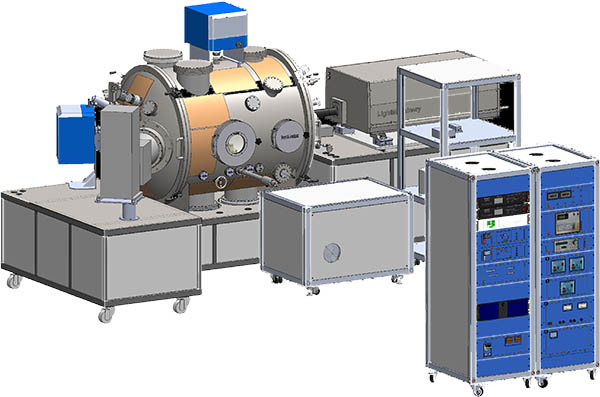
SimulTek is now offering a new generation of the AO space environment simulator. This simulator has a 0.6-0.8 m3 vacuum chamber, an oil-free pumping system (two turbo pumps FF-2000E and two scroll pumps IDP-15). Pressure in the vacuum chamber is: • with the source “off”: <10-7 Torr • with the source “on”: 3×10⁻⁵ Torr. Additional radiation sources may be located on this system: • Time-of-Flight (ToF) Sensors • Microwave AO Source (Optional) • 1-50 keV Proton Source • 1-50 keV Electron Source • Near Ultraviolet (NUV) Source (3-5 Equivalent Suns) • Near Ultraviolet (NUV) Source (3-10 Equivalent Suns) • Vacuum Ultraviolet (VUV) Source • Solar Simulator. Technical characteristics of these sources and devices are given in their description (see below) Both models have the same Atomic Oxygen source. It allows you to get the following parameters: • AO beam energy: controlled from 4~7eV (adjusted at 5eV) • Flux of AO (at 40 cm): > 5.0×10¹⁵ atoms/cm2/s • Operational frequency: 1-6 Hz • AO content: > 95% • Uniformity (at 40 cm): > 90% • Diameter of the AO beam (at 40 cm): > Ф200 mm • Time of continuous operation for AO source: ≥ 72 hrs, Time of continuous mechanical and electrical operation of the gas valve: ≥ 2 weeks • Automatic data acquisition and data logging for main operational parameters. This combined radiation + thermal cycling vacuum chamber allows simulation of the proton component of the low Earth orbit (LEO) radiation environment (protons, electrons, UV) to provide the possibility to expose the space-bound materials and spacecraft components to variable-energy high-intensity proton beams combined with a wide range of other factors (ultra-high vacuum conditions, temperature conditioning/ thermal cycling, fast atomic oxygen, etc.), with the basic proton beam characterization and analytical capabilities.
The Multifunctional LEO/GEO Space Environment Simulator Facility will include the following advanced technology factors Sources and specific components: • Vacuum Chamber with vacuum conditions: < 5×10⁻⁵ Pa (< 5×10⁻⁷ Torr) • Vacuum Pumping System (oil-free) • Sample Holder/Thermal Platform (from -1500C to +1500C at > 50C/min) • VUV Source (≥ Φ120 mm, 2-5 Equivalent VUV Suns) • NUV Source (≥ Φ120 mm, 2-5 Equivalent NUV Suns) • Data Acquisition System (pressure, temperature, VUV and NUV intensity) • Support Electronics and Control Software (Manual and Automatic Modes of Operation).